Myriad Build Guide
Kit Contents
| Component | Quantity |
|---|---|
| Myriad PCB | 1 |
| ELI2040c PCB | 2 |
| Panel | 1 |
| Capacitors | 4 |
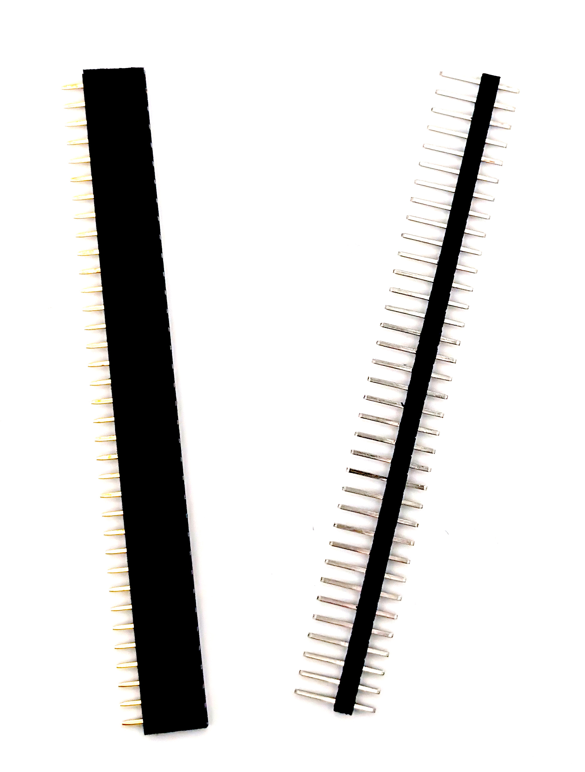
| 40 pin header male | 2 |
| 40 pin header male | 2 |
| 12mm spacer M3 | 2 |
| M3 screw 6mm | 2 |
| M3 nut for spacer | 2 |
| 6mm spacer M2 | 4 |
| M2 nut for spacer | 4 |
| M2 screw | 4 |
| Round TFT screen | 1 |
| Rotary encoder | 3 |
| B100k pot d shaft | 5 |
| A100k dual | 1 |
| Jack sockets + nuts | 9 |
| sifam knob d shaft (small skirt) | 8 |
| sifam knob T18 shaft (small skirt) | 1 |
| Lupin cap | 4 |
| Pale blue cap | 2 |
| Black encoder cap | 3 |
| Blue LED | 2 |
| Pink LED | 2 |
| IDC Cable | 1 |
Tools
You will need:
- Soldering equipment
- Crosshead screwdriver
- Pliers
- Cutters
Build Steps
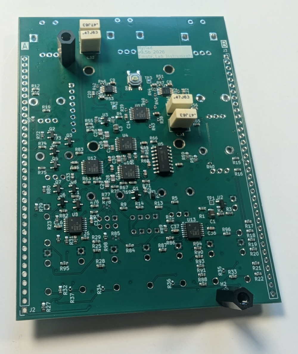
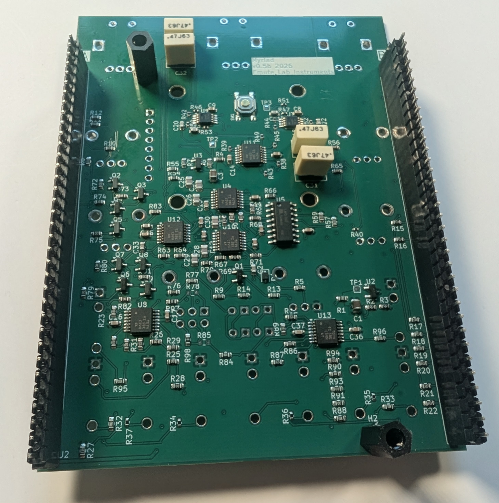
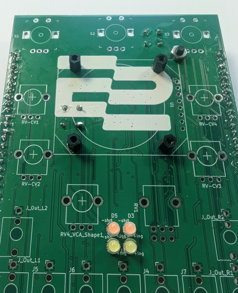
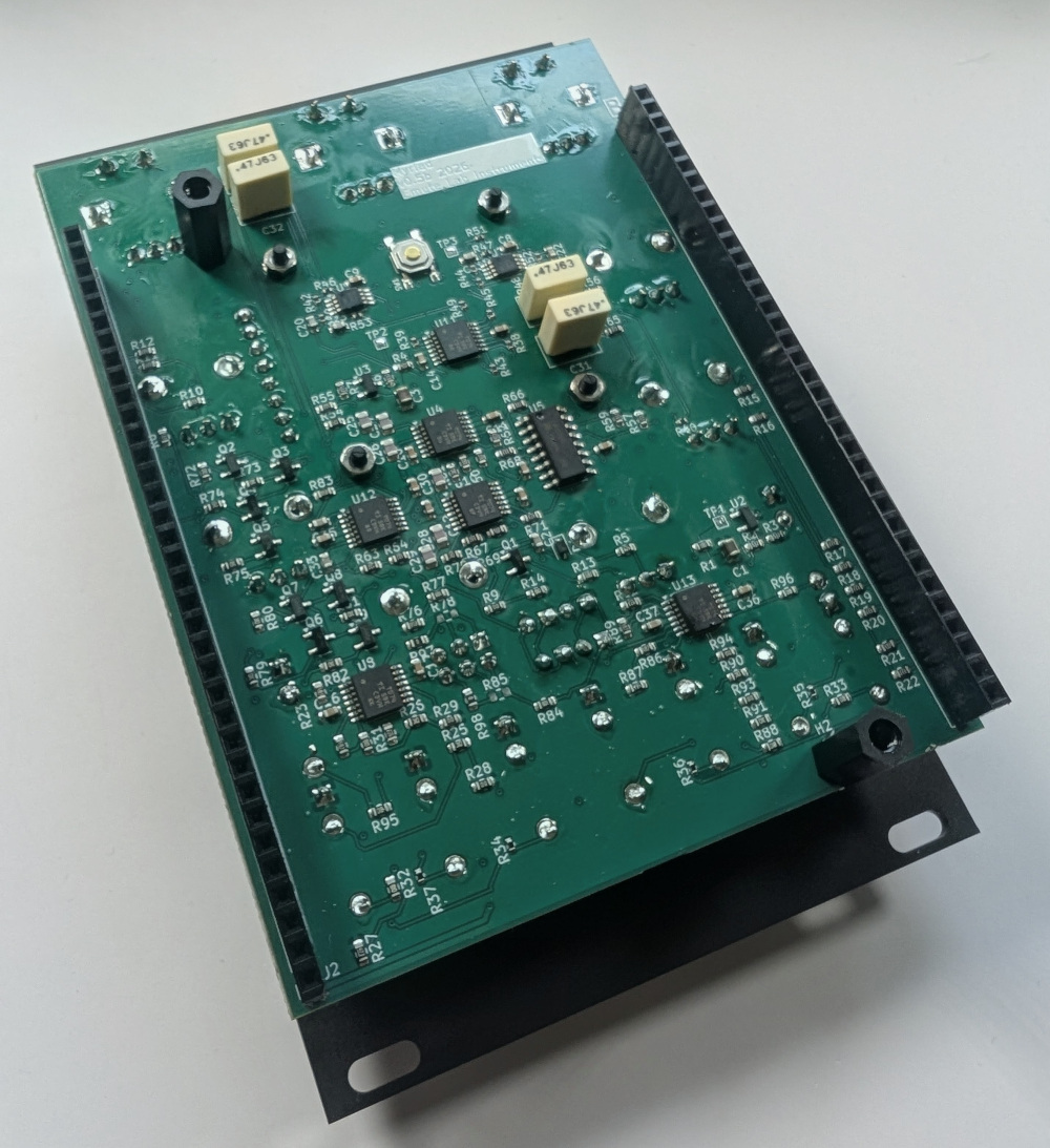
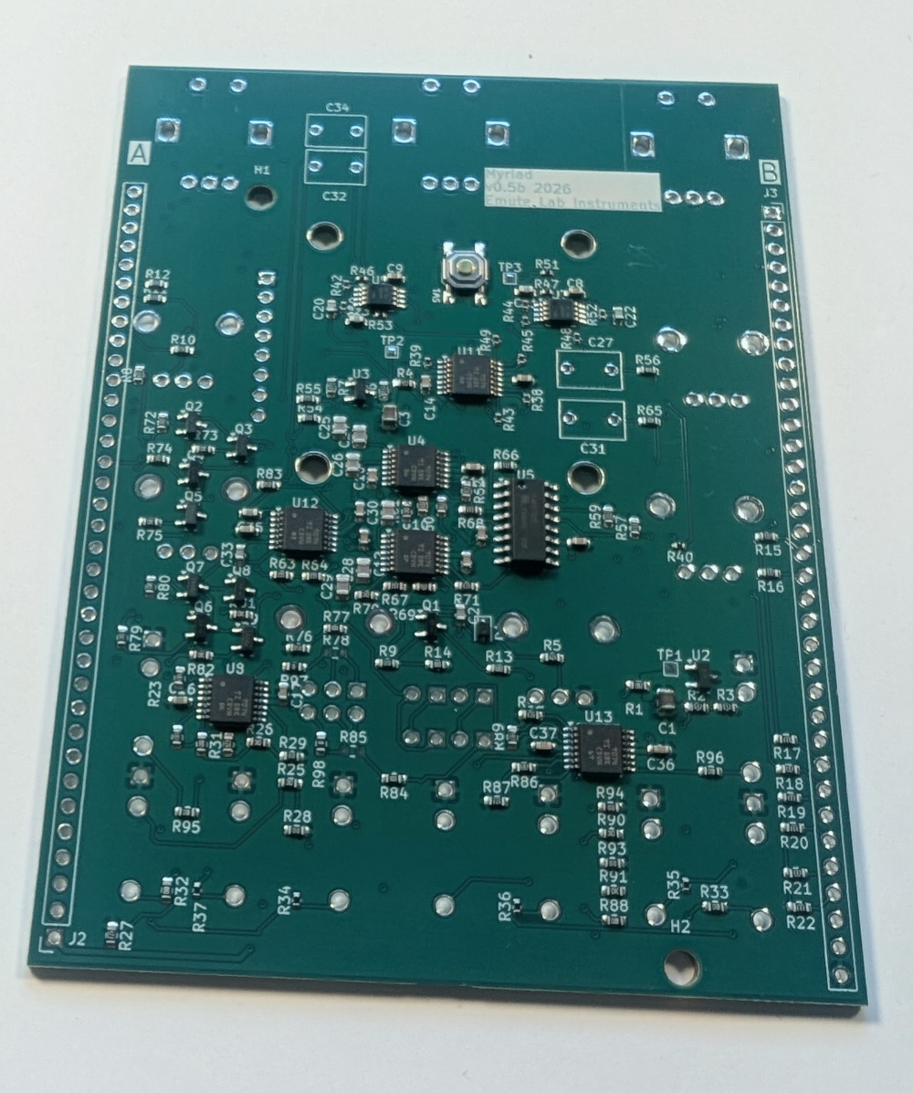 PCB Back
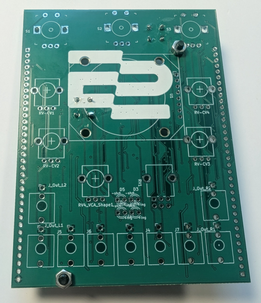
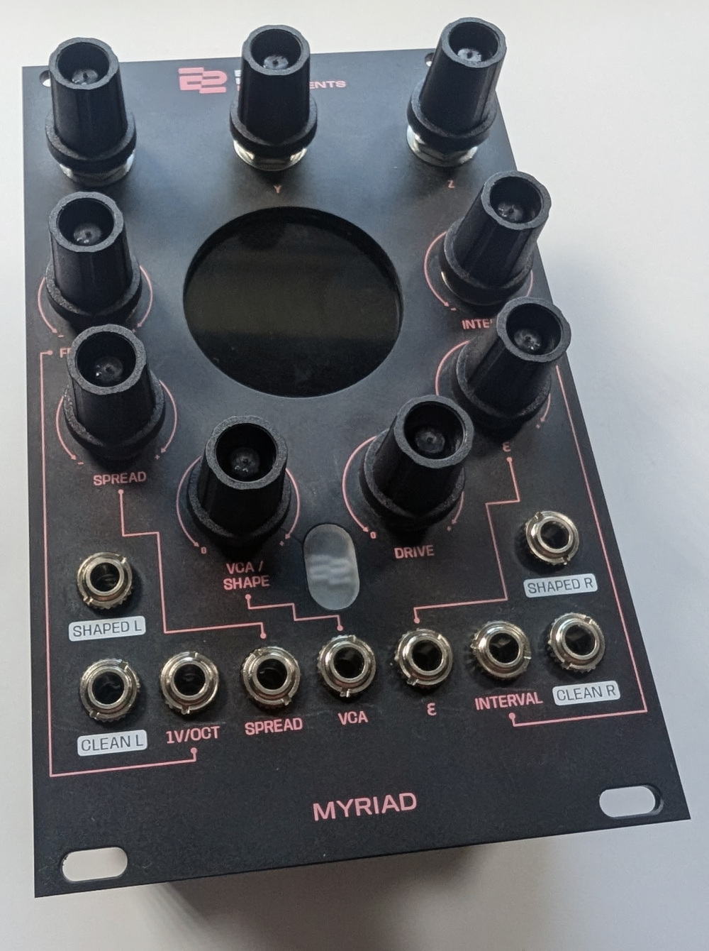
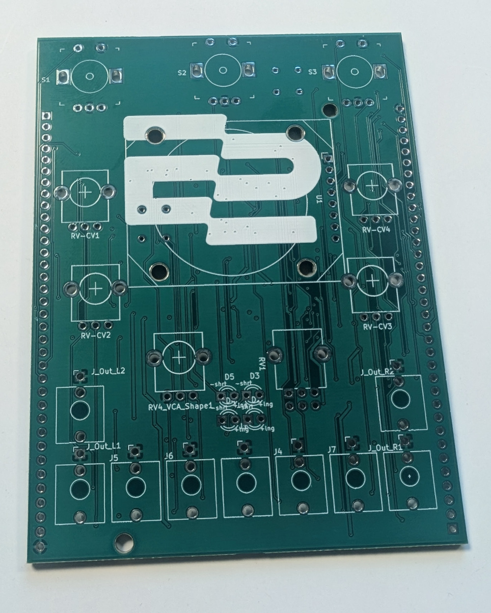 PCB Front
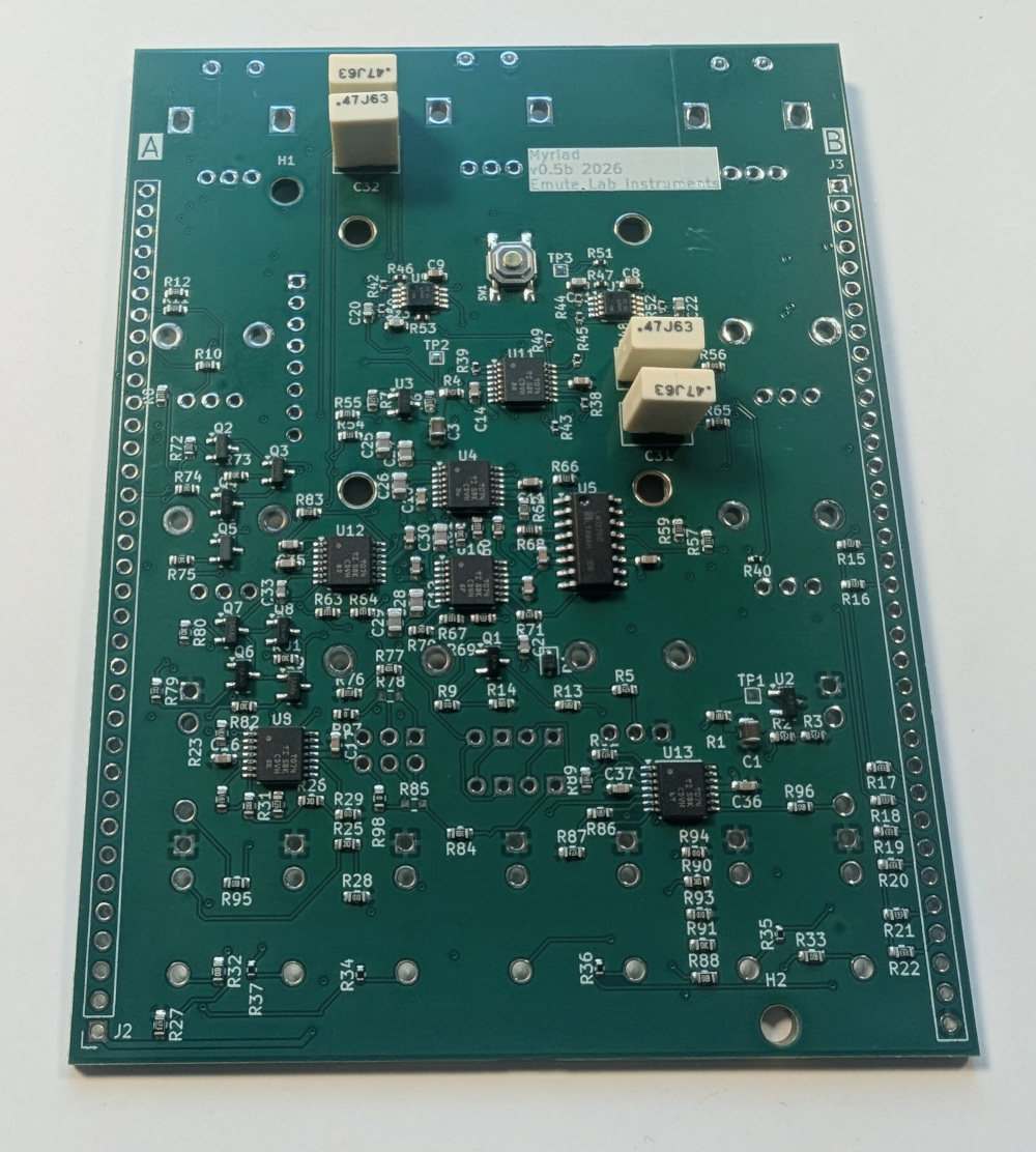
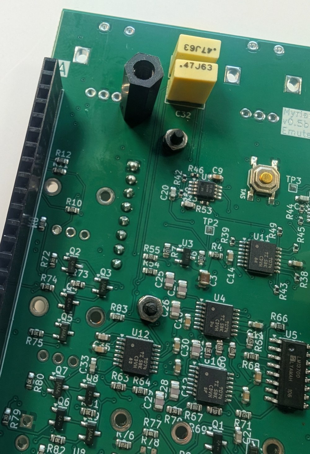
[1] Solder capacitors C27, C31, C32, C34
They are all identical, and non-polarised. Solder them to the back side of the board.
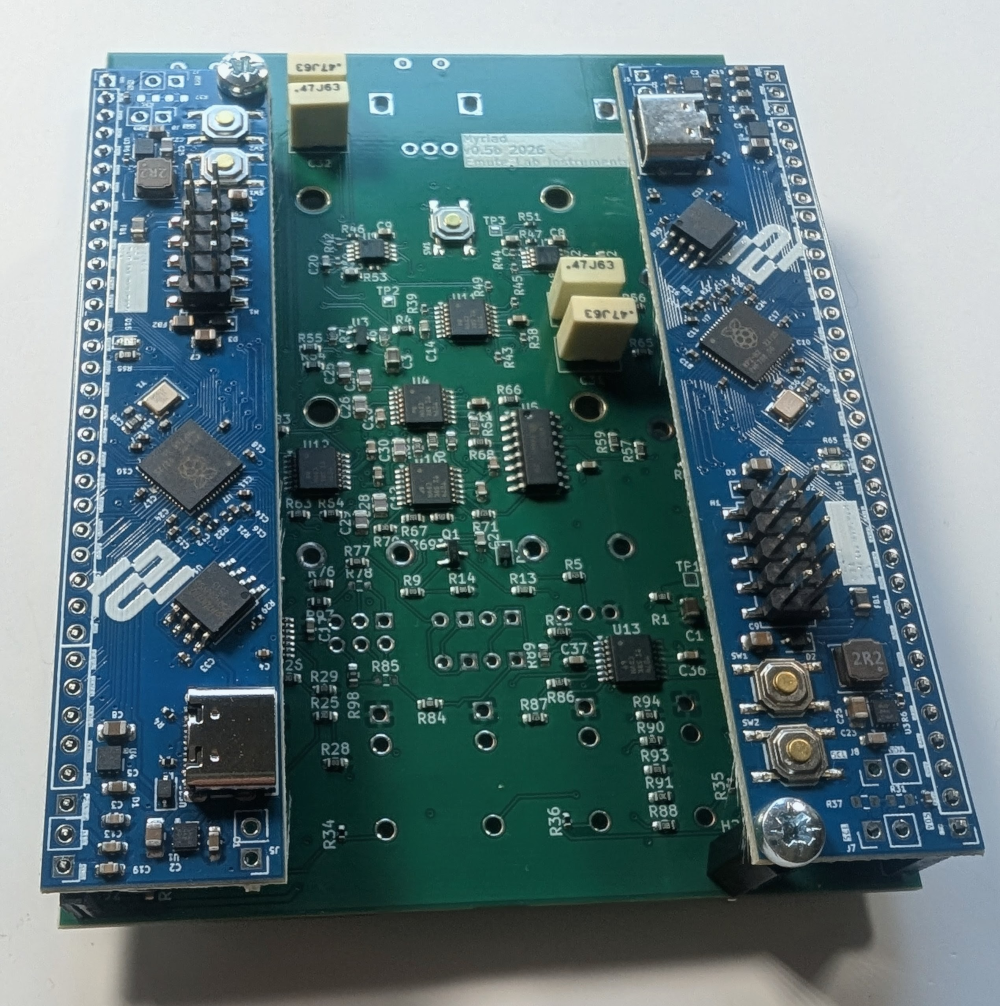
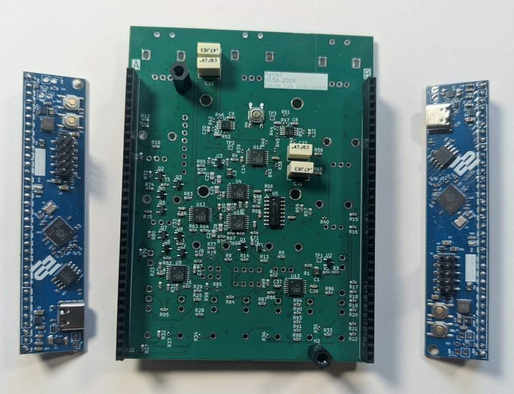
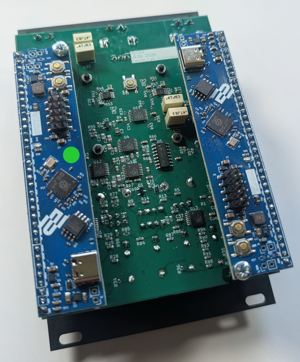
[2] ELI2040 boards
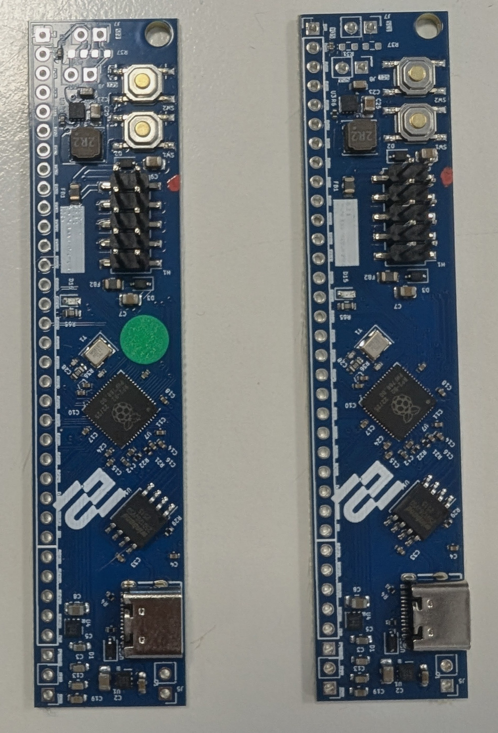
One of the boards has a green dot on it; this is the Myriad A unit, it should be placed on the left side of the back of the board. The Myriad B unit, without a green dot, goes on the right hand side.
[3] Clip the male pin headers to 35 pins long
Remove 5 pins from the end. This can be done by holding the 35th pin with pliers and snapping the other 5 off with your fingers. Be careful not to snap too many off.
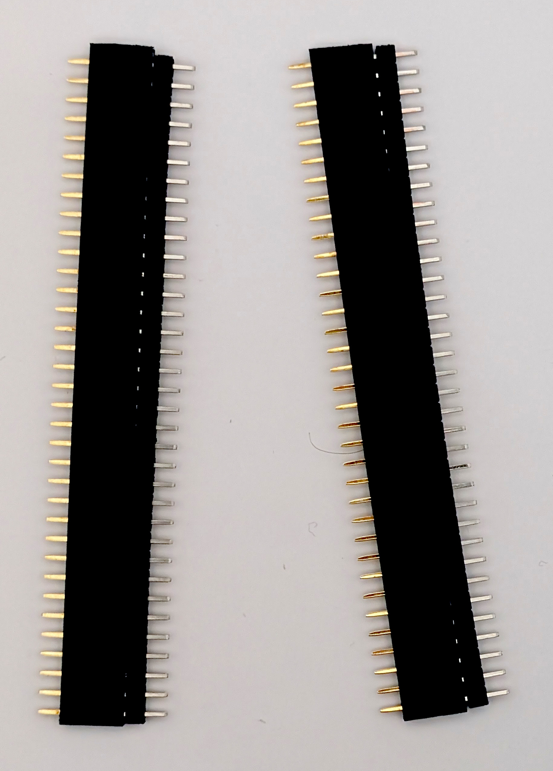
[4] Clip the female pin headers to 35 pins long
Cut direcly along pin 36, and then carefully trim excess plastic from the end
[5] Mount the 12mm spacers
Use M3 nuts on the front size, and twist the spacers until tight.
[6] Mount the ELI2040 boards and screw in the spacer
Place the male headers into the female headers and put the female headers onto the back side of the boar in J2 and J3. Mount the ELI2040 daughter boards on top, and secure to the spacer with an M3 screw.
[7] Solder the pins on both sides of the pin headers
[8] Unscrew the spacer screws and remove the ELI2040 boards
We’ll put them back later, but we need access to the back side for soldering.
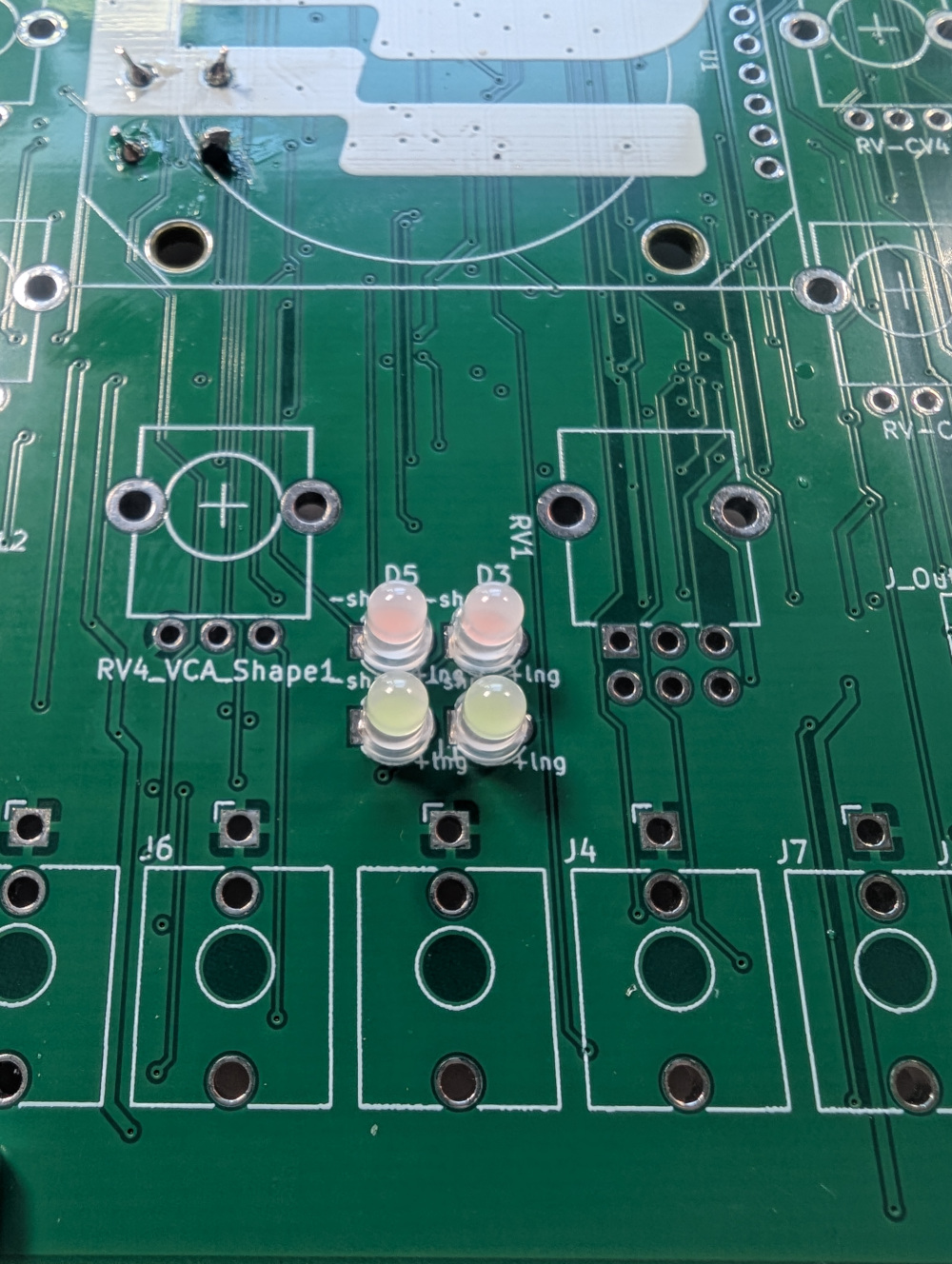
[9] Front side LEDs
Place the two pink LEDs in the top row, and the blue LEDs in the other. These should be flush to the PCB. It may help to tape the LEDs in place while you solder to ensure they are straight.
[10] Screen
Loosely mount the M2 spacers on the front side of the board.
Place the screen onto the board with the pins going through the holes. Screw and tighten up the M2 screws into the spacers, and then tighten up the nuts on the back side.
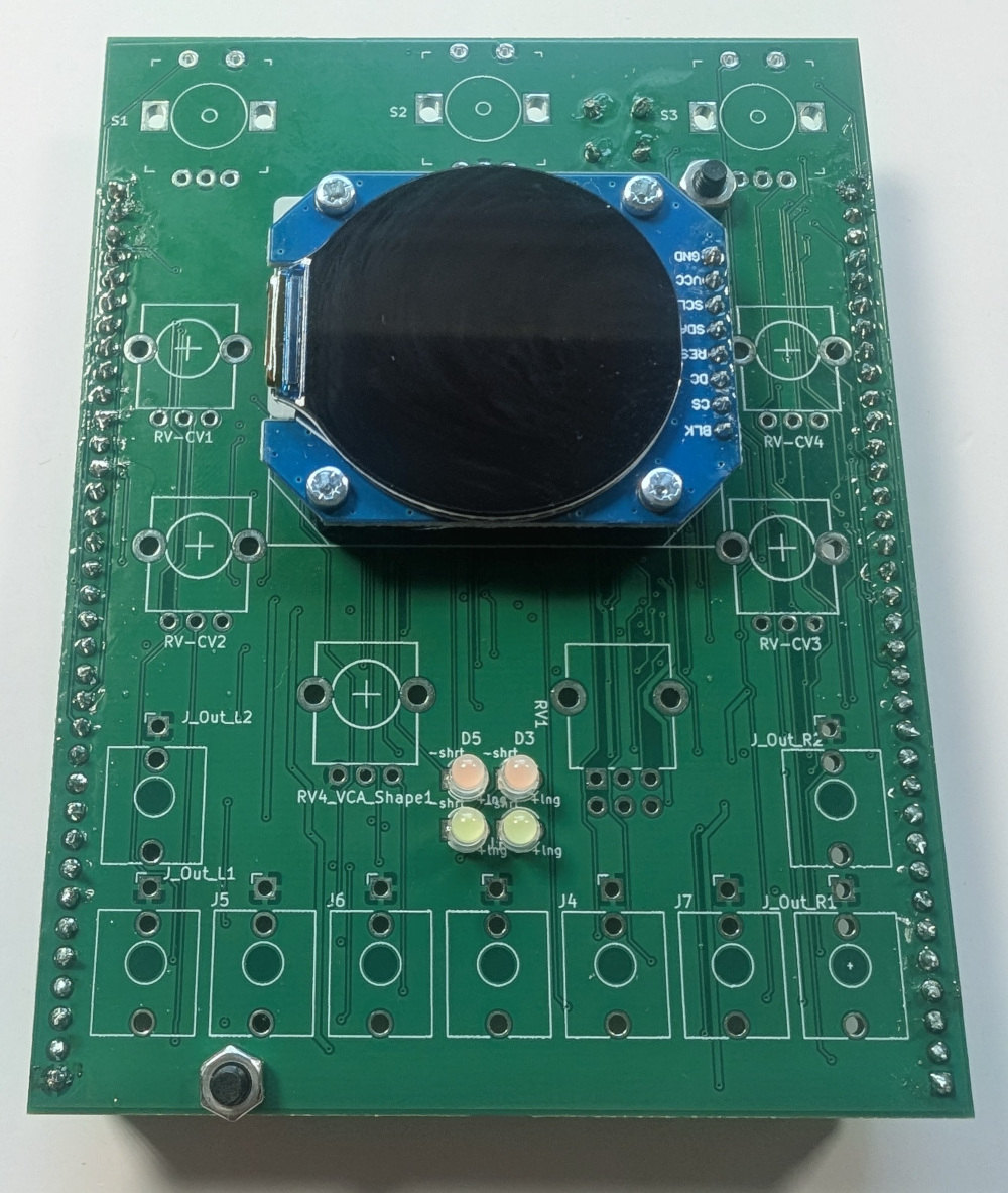
Now you can solder the screen pins. Peel away the plastic screen protector.
[11] Front side components
Mount the dual 100k pot in RV1, and then the 5 100k pots into RV-CV1-4 and RV4_VCA_Shape1. Mount the three rotary encoders at the top, and all the jack sockets.
Place the panel over the front components, and secure (loosely) with the nuts.
Solder the components, and then tighten up the nuts on the front panel.
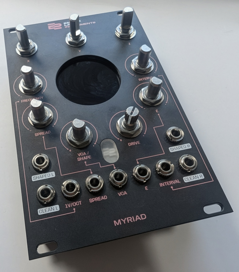
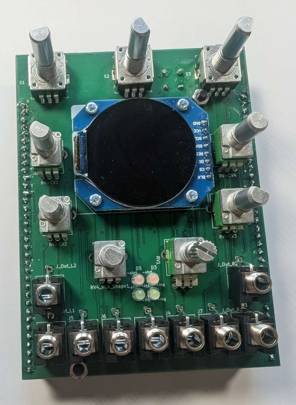
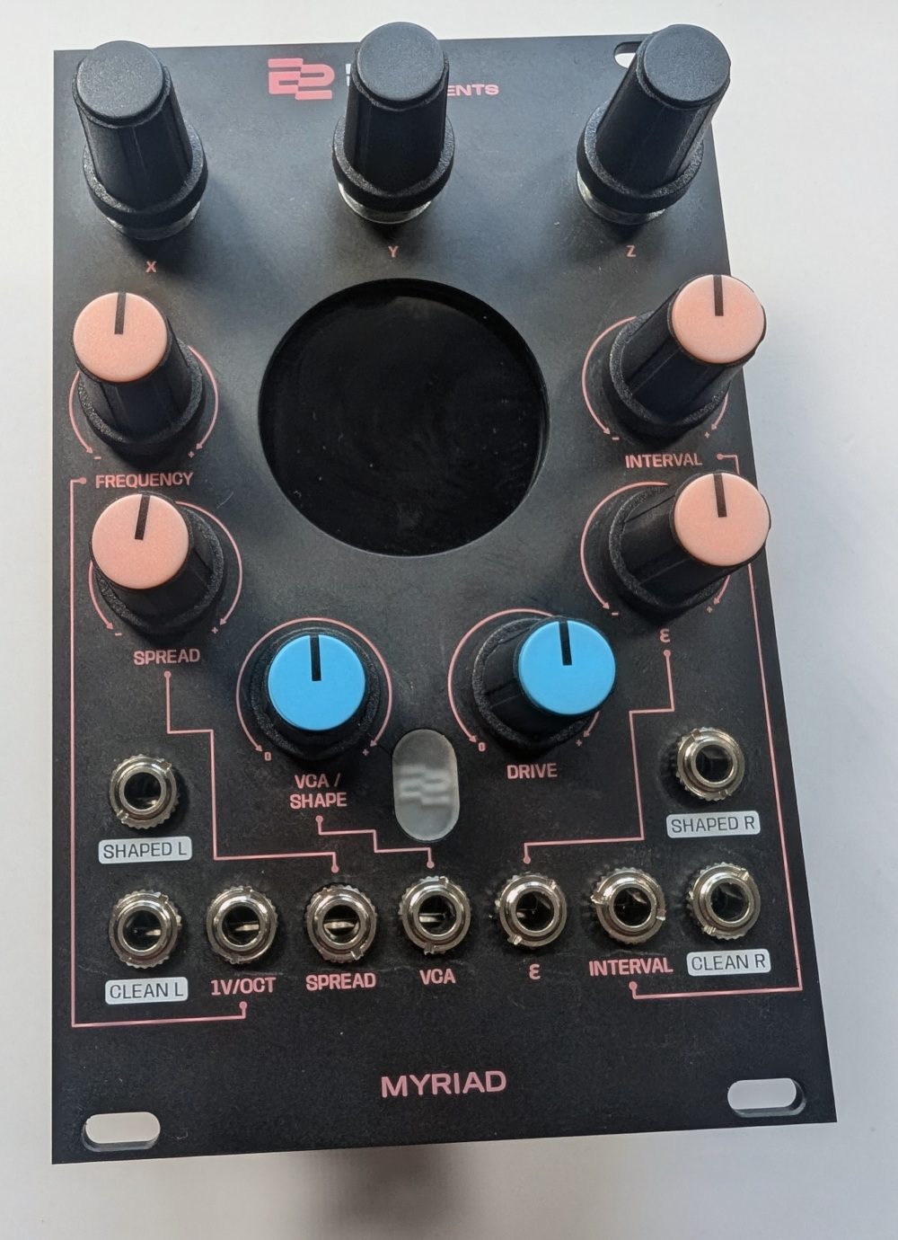
[12] Knobs
Mount the T18 shaft knob onto the overdrive pot shaft, and then the d-shaft knobs on the other pots.
Press in the coloured knob caps.
[13] ELI2040 boards
Remount the ELI2020 boards, making sure the unit with the green dot is on the left.
Reference Materials
The Kicad project is in our Git Repo